Researchers at the Department of Energy's Oak Ridge National Laboratory have developed the first additive manufacturing slicing computer application to simultaneously speed and simplify digital conversion of accurate, large-format three-dimensional parts in a factory production setting. The technology, known as Slicer 2, can help widen the use of 3D printing for larger objects made from metallic and composite materials. Objects the size of a house and beyond are possible, such as land and aquatic vehicles and aerospace applications that include parts for reusable space vehicles.
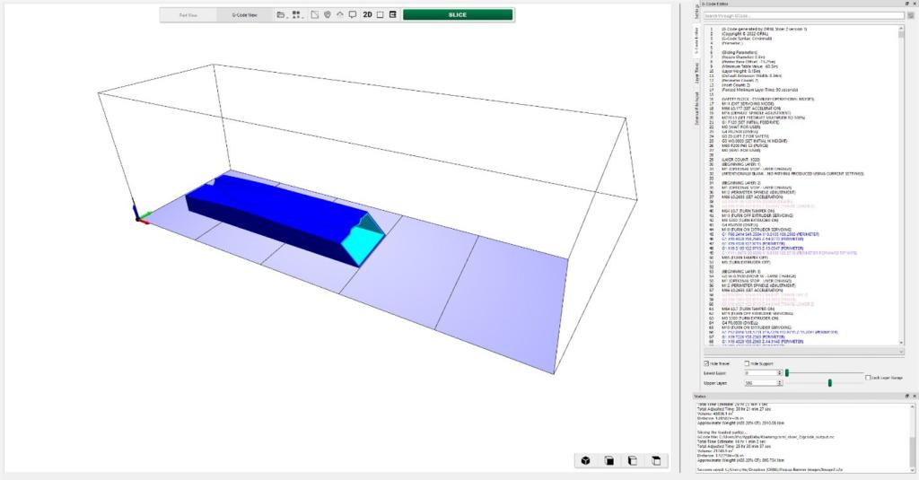
Slicing software converts a computer-aided design, or CAD, digital model into a series of two-dimensional layers called slices. It calculates print parameters for each slice, such as printhead path and speed, and saves the information in numerically controlled computer language. The computer file contains instructions for a 3D printer to create a precise 3D version of the image.
"The quality of a 3D-printed object is directly related to the accuracy and complexity of the toolpaths that control the machine's movements," said ORNL researcher Alex Roschli. "ORNL Slicer 2 software connects directly with various types of 3D printers to create an integrated platform and communicates with sensors to increase print accuracy."
Researchers designed ORNL Slicer 2 with more than 500 settings that control the internal structure, shape, temperature and other parameters of individual parts, layers or regions. It also interfaces with simulation software that shows complex heat and stress relationships during the additive manufacturing process. The software works with pellet thermoplastic, filament thermoplastic, thermoset, concrete, laser wire welding, MIG welding and blown-powder directed-energy deposition additive manufacturing systems.
"This connectivity translates into improved machine commands that increase reliability and repeatability of the additive manufacturing process," said Roschli. "The result of this software is that additive manufacturers can produce large factory parts with fewer machines and less cost than traditional machining methods."
Research for ORNL Slicer 2 is performed at the Department of Energy's Manufacturing Demonstration Facility at ORNL. The MDF, supported by DOE's Advanced Materials and Manufacturing Technologies Office, is a nationwide consortium of collaborators working with ORNL to innovate, inspire and catalyze the transformation of U.S. manufacturing. ORNL Slicer 2 is an open-source computer program available on GitHub and used by more than 50 equipment manufacturers, industrial end users and universities.
UT-Battelle manages ORNL for DOE's Office of Science, the single largest supporter of basic research in the physical sciences in the United States. DOE's Office of Science is working to address some of the most pressing challenges of our time. For more information, visit energy.gov/science.